Rack And Pinion Gear Design Pdf

Gear racks are utilized to convert rotating movement into linear motion.
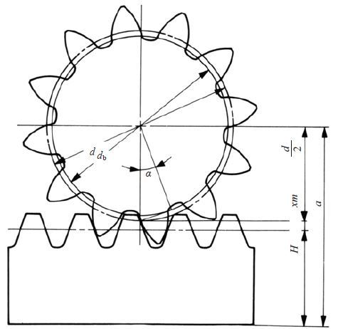
Rack and pinion gear design pdf. Rack and pinion steering one of the most common application is the rack and pinion steering. You benefit from minimum assembly work and fast start up. A circular gear called the pinion engages teeth on a linear gear bar called the rack. Modular system purchase the rack and pinion drive as individual components as a gearbox with matching pinion and rack.
Generally gear rack and pinion are collectively called rack and pinion. A rack and pinion is a type of linear actuator that comprises a pair of gears which convert rotational motion into linear motion. Rack and pinion combinations are often used as part of a simple linear actuator where the rotation of a shaft powered by hand or by a motor is converted to linear motion. Basic rack and.
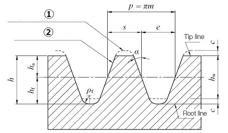
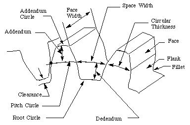
The tie rod at each end of the rack connects to the steering arm on the spindle. The components can be configured into a system quickly and economically. A gear rack has straight teeth cut into one surface of a square or round section of rod and operates with a pinion which is a small cylindrical gear meshing with the gear rack. The results of the design shows that weight of new rack and pinion gearbox is 20 less than the oem rpg with nearly 40 reduction in the cost achieving the desired steering ratio.
The rack carries the full load of the actuator directly and so the driving pinion is usually small so that the gear ratio reduces the torque required. It is the most common type of steering on cars small trucks and suvs. Rotational motion applied to the pinion causes the rack to move relative to the pinion thereby translating the rotational motion of the pinion into linear motion.


